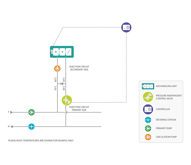
AIR HANDLING UNIT – PICV DIRECT CONTROL
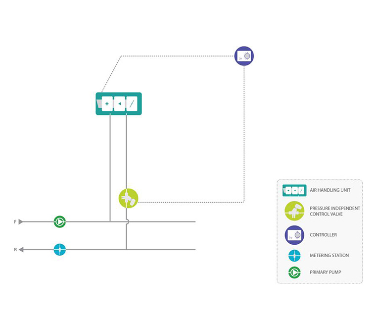
Air Handling Unit
with PICV direct control
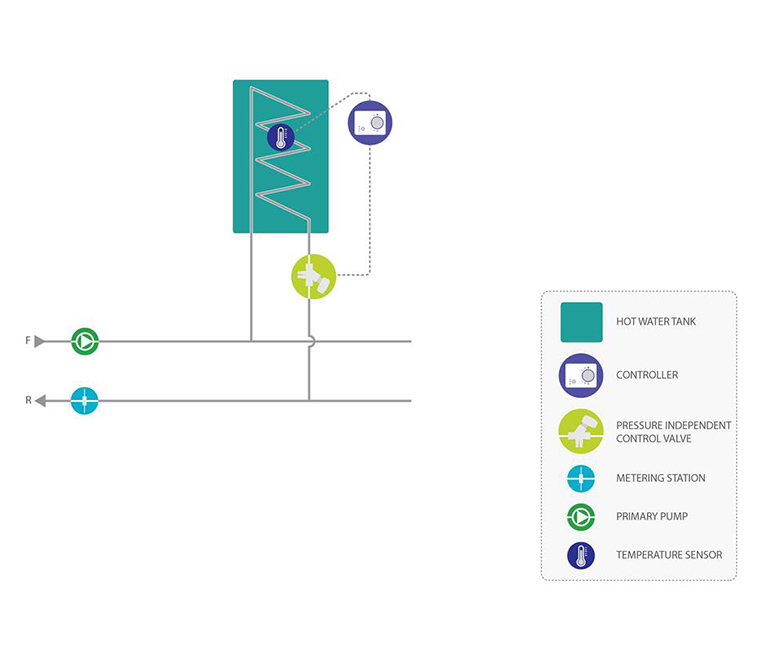
Function
The air temperature of the Air Handling Unit is controlled by a sensor in the outlet. When the control system calls for higher or lower temperature on the air outlet, the PICV opens or closes to increase or decrease the flow through the coil. The power output from the coil follows a parabolic curve where often an EQ% valve/actuator characteristic is chosen to have a direct relation between the input control signal and power output.
Benefits
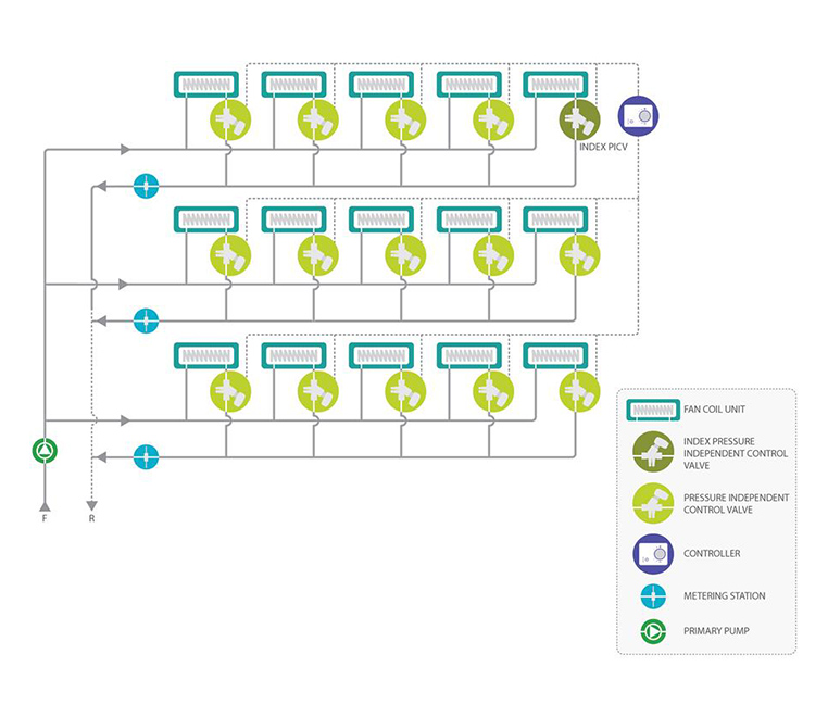
- The PICV ensures balancing of the primary flow and eliminates the use of both static balancing valves and differential pressure control valves.
- Simple application as only a PICV is required to control flow, temperature and differential pressure.
- At part load, the flow through the coil can be low leading to laminar flow and reducing the power output.
- Larger coils can have different temperatures in different areas of the coil making precise temperature control difficult.
- A metering station can be installed if additional flow verification is required.